
 9 min read




How to Read Electrical One-Line Diagrams for a More Complete Takeoff
Electrical takeoffs are rarely completed from a single plan sheet. Floor plans may show where devices and panels are located, while schedules define circuit information and equipment ratings. But when an estimator needs to understand how a building’s power distribution system connects from the utility source to downstream equipment, the electrical one-line diagram is one of the most important drawings in the set.
Also called a single-line diagram or SLD, a one-line diagram simplifies a three-phase electrical distribution system into a single-line representation. For estimating purposes, it can reveal major equipment, feeder relationships, voltage changes, overcurrent protection, emergency power connections, and scope that may not be obvious on floor plans. Learning how to read electrical one-line diagrams helps an estimator build a more complete electrical takeoff and reduces the chance of missing high-value distribution items.
What Is an Electrical One-Line Diagram?
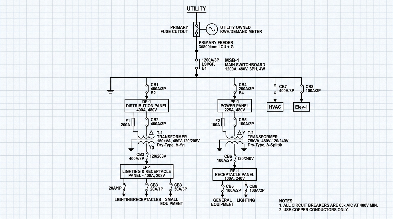
An electrical one-line diagram is a simplified drawing that shows how electrical power flows through a building or facility. Instead of showing every conductor individually, it uses one line and project symbols to represent the major distribution path. Depending on the project, the one-line may show utility service, switchgear, switchboards, panelboards, transformers, circuit breakers, fused switches, feeders, disconnects, motor control centers, generators, automatic transfer switches, UPS equipment, metering, grounding, and major loads.
The exact symbols and abbreviations can vary between designers, so review the drawing legend and general notes before taking quantities. For an estimator, the value of the one-line is not simply understanding how the system works. It is identifying what must be quantified, priced, coordinated, or verified elsewhere in the electrical documents.
Why One-Line Diagrams Matter in an Electrical Takeoff
A complete electrical takeoff must account for more than receptacles, light fixtures, switches, and branch circuits. Distribution equipment and feeders can represent a substantial portion of the material and labor cost of a commercial electrical project. A floor plan may show the location of a panel, but it may not clearly tell you what feeds that panel. The one-line can show the upstream switchboard, breaker, transformer, feeder designation, voltage, and related distribution information.
That makes it especially useful for identifying major switchboards, distribution panels, primary and secondary feeders, transformers, service equipment, emergency power equipment, voltage transitions, disconnects, and connections between distribution components. The goal is not to use the one-line in isolation. A reliable electrical estimate comes from reconciling it with panel schedules, floor plans, feeder schedules, specifications, riser diagrams, details, and equipment schedules.
1. Start With the Legend, Notes, and Latest Revision
Before tracing the system, confirm that you are working from the latest issued drawing set.
Check the sheet title, revision number, addenda, general notes, and electrical legend. Symbols used for breakers, transformers, disconnects, generators, panelboards, and other equipment may differ between engineering firms.
Also look for notes defining scope boundaries. Some equipment may be furnished by the owner, utility company, mechanical contractor, or another trade while still requiring electrical connections. Those notes can change what material, labor, terminations, testing, or coordination belongs in your bid.
2. Find the Utility or Main Power Source
Most one-line diagrams are read from the power source toward the loads. The source is commonly shown near the top or left side of the sheet. Identify the incoming service and record the service voltage, phase and wire configuration, main service rating, metering, main disconnect, and service entrance equipment.
For example, a commercial project may have a 480Y/277V service feeding a main switchboard. Downstream transformers may step the voltage down to 208Y/120V for receptacles and other loads. Recognizing that voltage transition early helps explain why transformers and separate distribution panels appear later in the system.
3. Identify Major Distribution Equipment
Follow the one-line from the service to each major piece of downstream equipment and create an equipment list as you go. Common items include switchgear, switchboards, distribution panels, panelboards, motor control centers, transformers, disconnects, enclosed breakers, automatic transfer switches, generators, and UPS equipment.
Record equipment tags exactly as they appear. A tag such as MSB-1, DP-1, LP-1, or T-1 lets you cross-reference the same item on panel schedules, floor plans, equipment schedules, and specifications. Do not rely only on the symbol. Read the notes beside the equipment for amperage, voltage, kVA, breaker size, configuration, and other pricing information.
4. Trace Transformers and Voltage Changes
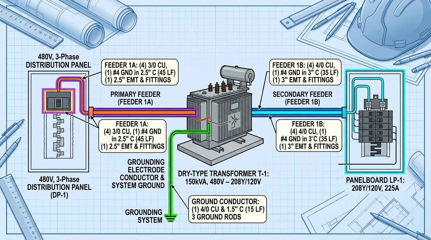
Transformers are easy to count, but they can create additional scope that is missed when the estimator stops at the equipment quantity. For each transformer, note its tag, kVA rating, primary voltage, secondary voltage, phase, upstream protection, and downstream equipment. Then trace both sides of the transformer.
The primary side may require a feeder and disconnect or breaker. The secondary side may feed a panelboard or distribution panel through another feeder. Grounding, supports, terminations, and accessories may also affect the estimate depending on the project documents. This is why one transformer symbol can represent more than one takeoff line item.
5. Build the Feeder Takeoff From the Distribution Path
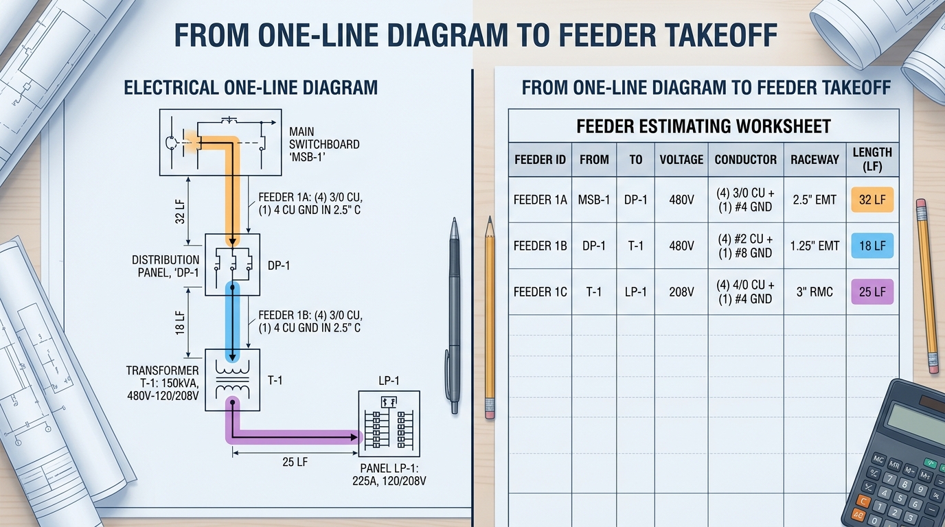
Feeders are one of the most important reasons estimators review one-line diagrams. Trace every connection between major equipment and build a feeder list with a clear “from” and “to” relationship, such as:
MSB-1 → DP-1
DP-1 → T-1
T-1 → LP-1
Then cross-reference the feeder designation with feeder schedules, panel schedules, notes, and specifications to determine conductor and raceway requirements. A feeder takeoff may include conductor size and quantity, conductor material, raceway size and type, parallel sets, grounding conductor, measured length, vertical rise or drop, fittings, supports, pull boxes, terminations, sleeves, firestopping, or trenching.
The one-line establishes the electrical relationship. Other drawings help determine routing and measurable length. Pricing a feeder from only one document increases the risk of missing scope.
6. Review Breakers, Disconnects, and Protective Devices
As you trace the system, note main breakers, feeder breakers, fused switches, disconnects, and other protective devices. Record their ratings and identify whether they are integral to equipment or separate items that need to be taken off individually.
This is especially important around mechanical equipment, transformers, generators, and large loads. A floor plan may show the equipment location while the one-line or schedule reveals the required disconnect or upstream protection. Specifications may also define enclosure types, accessories, ratings, and manufacturer requirements that affect pricing.
7. Follow Emergency and Standby Power Separately
Commercial electrical drawings may include a separate power path for emergency or standby systems. Look for generators, automatic transfer switches, emergency distribution panels, life-safety branches, UPS equipment, battery systems, and dedicated emergency feeders.
Trace both the normal and emergency sources through the transfer equipment to downstream loads. These systems can create feeders, controls, disconnects, equipment, and testing scope that is easy to miss when reviewing only normal-power plans. Keep normal and emergency quantities separated in the takeoff so they can be priced and checked independently.
8. Reconcile the One-Line With Panel Schedules and Floor Plans
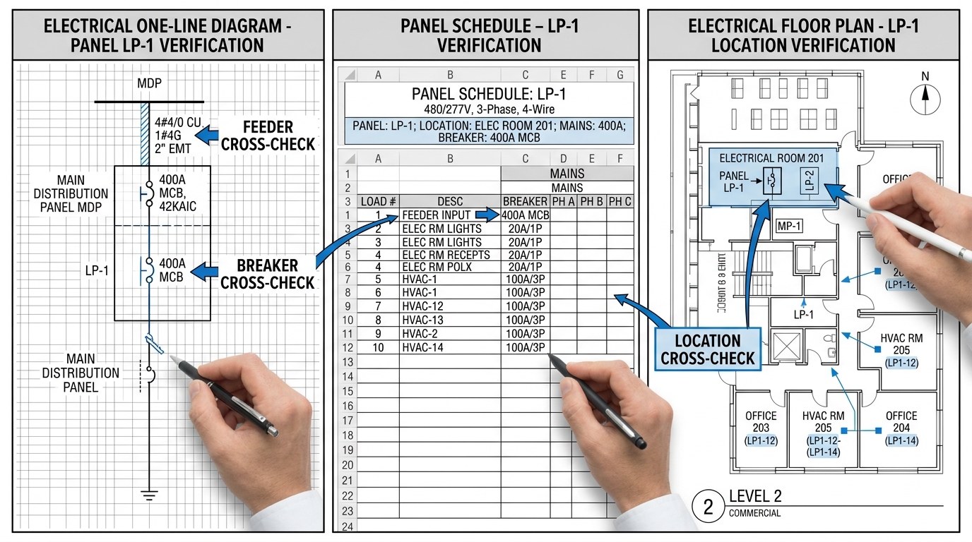
A one-line provides the distribution hierarchy, but it does not replace the rest of the electrical set. Compare each equipment tag and feeder with the panel schedules and floor plans. Confirm that panels shown on the one-line appear on the plans and that voltage, main rating, and feeder information are consistent.
If the documents conflict, flag the discrepancy rather than making an unsupported assumption.
This cross-check also prevents duplicate takeoff. A panelboard may appear on the one-line, floor plan, and schedule, but it should still be counted as one piece of equipment.
What Should You Extract From a One-Line for Estimating?
A practical one-line takeoff worksheet can include these fields:
ItemTagFromToVoltageRatingFeederNotesMain switchboard | MSB-1 | Utility | MSB-1 | 480Y/277V | 1200A | Service | Verify specs |
Transformer | T-1 | DP-1 | LP-1 | 480V → 208Y/120V | 75 kVA | F-12/F-13 | Include both sides |
Panelboard | LP-1 | T-1 | Branch circuits | 208Y/120V | 225A | F-13 | Check schedule |
This creates a clear bridge between drawing review and detailed pricing.
Common One-Line Takeoff Mistakes
Common estimating errors include counting equipment but missing its feeders, pricing a transformer without the secondary distribution scope, overlooking emergency power, relying only on the floor plan for feeder information, failing to cross-check schedules, and counting the same equipment twice because it appears on multiple sheets.
The solution is simple: use equipment tags and feeder relationships as your control system. Every major component should be traceable through the drawing set, and every feeder should have a defined source and destination.
One-Line Diagram vs. Riser Diagram vs. Panel Schedule
These documents support different parts of the estimate.
A one-line diagram shows the overall electrical distribution path and major equipment relationships.
A riser diagram typically emphasizes vertical distribution through floors or building levels.
A panel schedule gives detailed information about a specific panel, including circuits, loads, breaker sizes, and other panel data.
A complete commercial electrical takeoff may require all three. The estimator’s job is to connect the information rather than treating each drawing independently.
Use the One-Line as a Scope Map, Not a Standalone Takeoff
The best way to use an electrical one-line diagram is as a scope map.
Start at the source, trace every major distribution path, record each piece of equipment, identify every feeder relationship, then verify those items against the rest of the construction documents. That process helps create a more complete electrical takeoff because it exposes expensive distribution scope that can be missed when an estimator focuses only on device counts and floor-plan measurements.
For contractors bidding multiple projects or working with limited estimating capacity, professional electrical estimating services can provide a structured takeoff covering distribution equipment, feeders, branch circuits, lighting, devices, and other Division 26 scope. The principle is the same: every quantity should be traceable to the drawings and coordinated across the full electrical set.
Frequently Asked Questions
What is the difference between a one-line diagram and a single-line diagram?
There is generally no practical difference. “One-line diagram” and “single-line diagram” are commonly used for the same simplified representation of an electrical distribution system.
Can you complete an electrical takeoff from the one-line diagram alone?
Usually not. The one-line is excellent for understanding distribution, but accurate quantities often require floor plans, panel schedules, feeder schedules, specifications, details, and equipment schedules.
What should an estimator look for first on an electrical one-line diagram?
Start with the drawing legend and revision, then find the utility or main power source. From there, trace the system through switchgear, transformers, panelboards, feeders, and major loads.
Why are one-line diagrams important for electrical estimating?
They help estimators understand how major equipment connects, identify feeder relationships, spot voltage changes, and capture distribution scope that may not be obvious on floor plans.