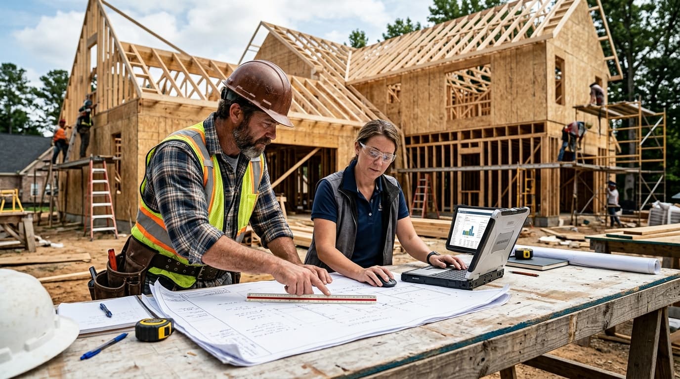
 9 min read




How to Read Structural Steel Plans for a More Complete Bid
Reading structural steel plans accurately can make the difference between a bid that covers the full scope and one that leaves costly work behind. Structural drawings communicate much more than beam and column sizes. They show framing layouts, elevations, connections, plates, bracing, embeds, welds, bolts, and notes that can affect material, fabrication, erection, labor, equipment, and coordination.
For estimators, subcontractors, fabricators, and general contractors, the goal is not simply to understand what the building looks like. The goal is to convert the drawings into a complete, reviewable scope that can be priced with confidence. This guide explains how to read structural steel plans step by step, what to look for during a steel takeoff, and which details are commonly missed before bid day.
Start With the Drawing Index, Title Block, and Revisions
Before measuring a single beam, confirm that you are working from the correct drawing set.
Review the drawing index to identify the structural sheets, commonly labeled with an “S” prefix. Then check the title block for the project name, drawing number, issue date, scale, and revision information.
This matters because a clear drawing can still produce a bad estimate if it is outdated. Addenda may change beam sizes, column locations, deck areas, connection requirements, or elevations.
During estimating:
- Confirm the latest structural drawing issue.
- Review addenda and revision clouds.
- Check whether architectural plans changed too.
- Note missing structural sheets or referenced details.
- Record assumptions when the bid set is incomplete.
A more complete bid begins with controlling the information you are pricing.
Read the General Structural Notes Before the Framing Plans
General notes define rules that apply across the project. Estimators sometimes skip directly to framing plans because that is where most quantities appear, but the notes can change the cost of those quantities. Look for structural steel grades, HSS requirements, bolts, welds, deck, headed studs, shop primer, galvanizing, fireproofing preparation, special inspections, and delegated connection design.
The American Institute of Steel Construction maintains standard shape data and naming conventions used throughout U.S. structural steel documents. Those member designations are important estimating references when converting plan callouts into lengths and weights. The notes may also identify cost drivers that are not obvious on the plan. A member may require galvanizing, a connection may require special bolting, or exposed steel may need a higher finish standard.
Understand Grid Lines and Structural Levels
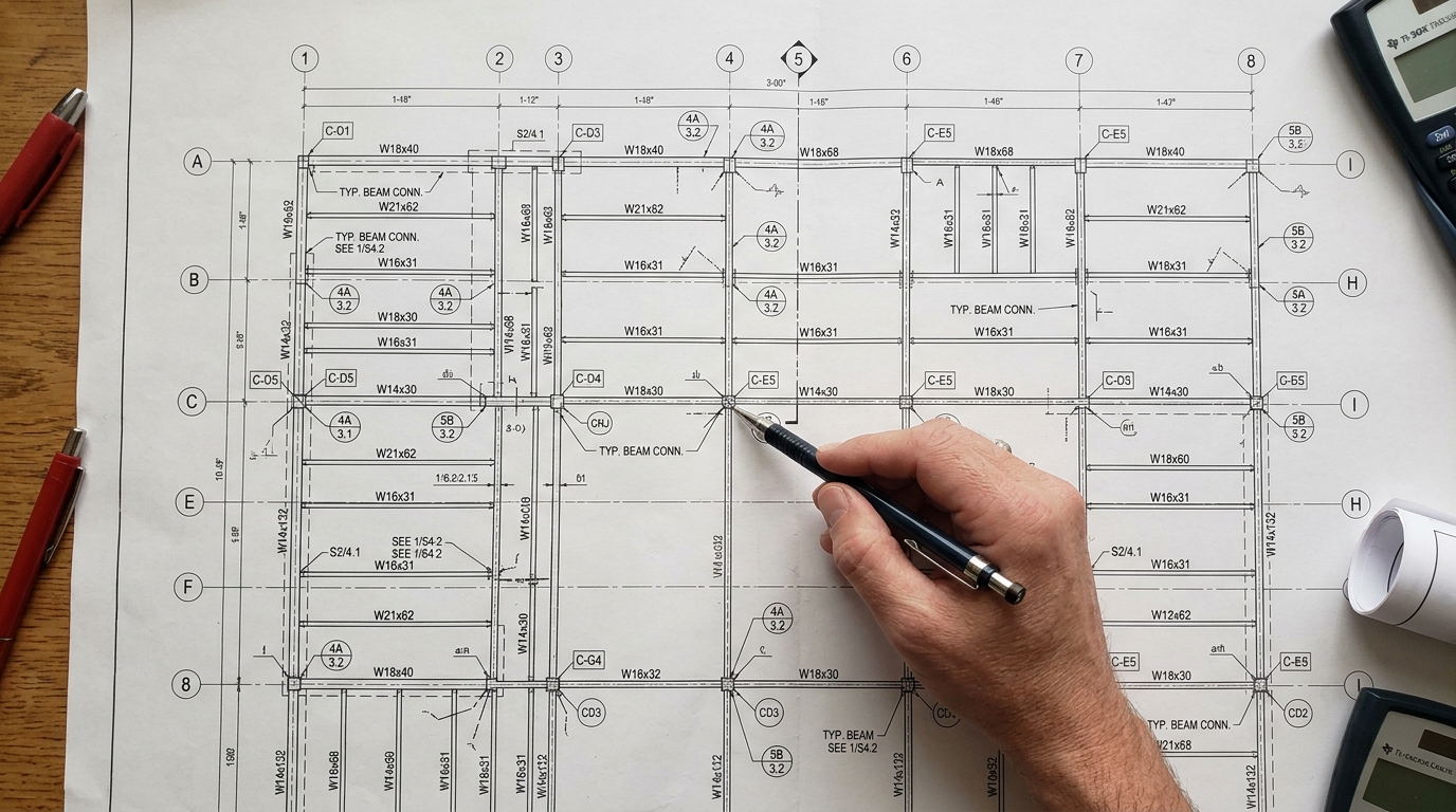
Grid lines are the coordinate system of a structural drawing. Letters usually identify one direction and numbers the other. Columns, beams, braces, walls, and openings can then be located by grid intersection. For example, a column at Grid B/4 can be followed through foundation plans, floor framing plans, roof plans, elevations, and details.
Also check levels and elevations. Steel framing may step, slope, cantilever, or change elevation between bays. Roof steel is especially easy to misread where plans include multiple slopes or top-of-steel elevations. Separating takeoff quantities by level or area can make the estimate easier to audit and can expose duplicated or missing framing.
Learn the Most Common Structural Steel Member Callouts
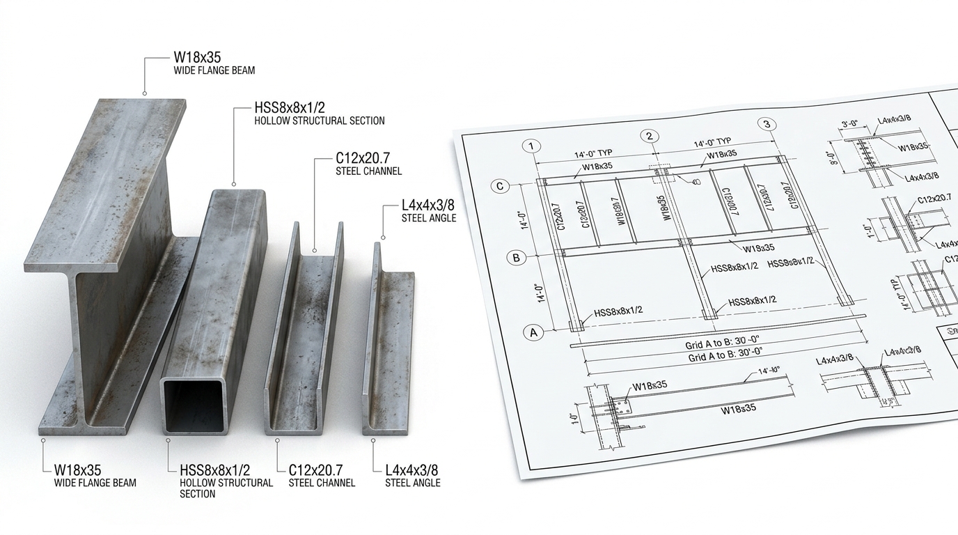
Structural steel plans use standardized member labels to identify shapes and sizes. A callout such as W18x35 identifies a wide-flange shape. The “18” represents the nominal depth and “35” the nominal weight in pounds per linear foot.
Other common callouts include:
- HSS8x8x1/2 for a square hollow structural section.
- C12x20.7 for a channel.
- L4x4x3/8 for an angle.
- WT shapes for structural tees.
- PL callouts for plates.
- Joist designations for open-web steel joists.
For bidding, do not stop at recognizing the shape. Record the member size, length, quantity, level, location, and any special note. A beam with the same section size as another may still cost more if it requires camber, studs, special connections, field welding, or difficult erection.
Read the Framing Plan as a Complete System
The structural framing plan is usually the primary quantity source for beams, girders, columns, joists, and bracing. Work through it systematically instead of jumping between visible labels. One practical method is to start at one grid corner and move bay by bay.
Check for:
- Beams, girders, columns, and HSS framing.
- Braces and moment frames.
- Joists and joist girders.
- Roof or floor openings.
- Edge framing and cantilevers.
- Transfer members and equipment support steel.
- Stairs and miscellaneous framing.
- Top-of-steel elevations.
- Detail and section references.
When repeated bays look identical, verify that they actually are. A single note, opening, elevation change, or connection symbol can make one bay different.
Follow Members Into Sections and Details
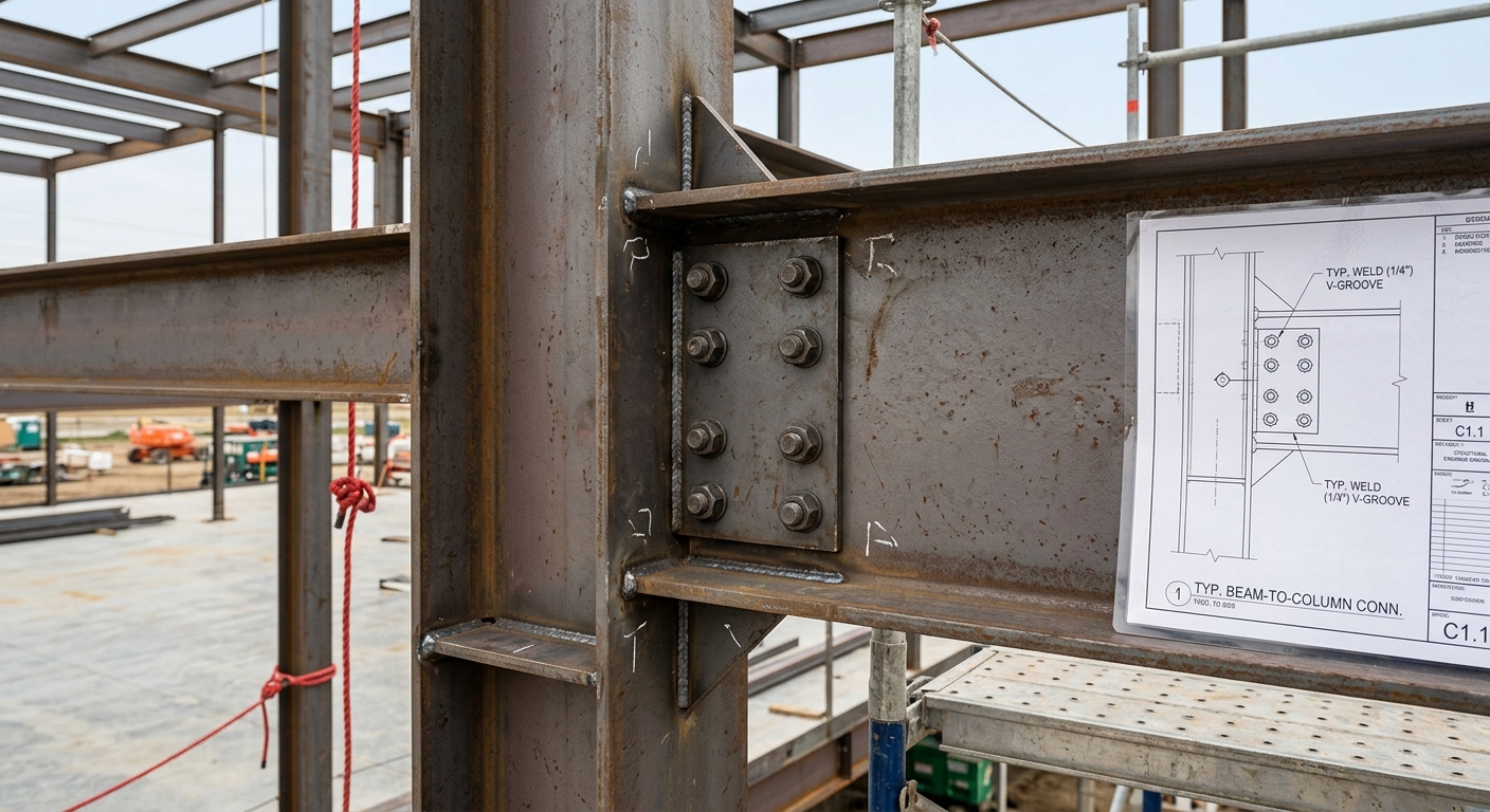
A framing plan tells you where a member is located, but it rarely tells you everything required to price it. When a beam or column references a section or detail, follow that callout. Sections can reveal plates, stiffeners, copes, bearing conditions, welded attachments, offsets, reinforcing, and support conditions that are not clear in plan view.
A useful estimating habit is to ask: What supports this member? What connects to it? Are plates, angles, bolts, or welds required? Does another trade interface with it? Is there a special elevation or erection condition? Those questions turn a basic member count into a more complete structural steel takeoff. For larger or more complex bid packages, professional quantity takeoff services can organize these drawing-based quantities into a measurable and reviewable scope before pricing begins.
Review Connection Details, Bolts, and Weld Symbols
Connections can represent a major portion of fabrication labor and hardware cost, especially on projects with braced frames, moment connections, transfer framing, or specialty details. Review shear connections, moment connections, brace connections, base plates, splice plates, clip angles, gusset plates, stiffeners, and field connections.
Welding symbols should also be read carefully. AWS A2.4 establishes conventions for welding symbols used to communicate weld requirements on drawings. Estimators do not need to perform connection engineering, but they should recognize when the documents require different types or extents of welding. Bolt quantities and installation requirements also affect material and labor. If connection design is delegated and final details are unavailable, identify that uncertainty in the estimate instead of silently assuming zero cost.
Check Schedules Instead of Relying Only on Plan Labels
Structural plans often use schedules to organize repeated information. Common examples include beam, column, base plate, lintel, joist, and connection schedules. When a plan shows a mark such as B1, C3, or BP2, the schedule may contain the information required to price that member.
Cross-check the schedule against the plan count. If a schedule appears to list twenty members but the framing plan shows twenty-two marks, investigate the difference. Schedules are also useful quality-control tools for identifying missing sizes or unusual quantities.
Capture the Items Commonly Missed in Steel Bids
The most expensive omissions are not always the largest beams. Small components can multiply across the project and create meaningful cost. Check for base plates, anchor rods, bearing plates, stiffeners, shear tabs, clip angles, gusset plates, kickers, edge angles, loose lintels, shelf angles, embeds, stairs, ladders, rails, equipment frames, and deck accessories when they are part of the steel scope.
Also review coatings, galvanizing, touch-up, freight, cranes, mobilization, field welding, temporary bracing, and special inspection requirements. Your exclusions should be as deliberate as your inclusions. If an item belongs to another subcontractor, state the boundary clearly instead of simply leaving it out.
Coordinate Structural Steel With Masonry Scope
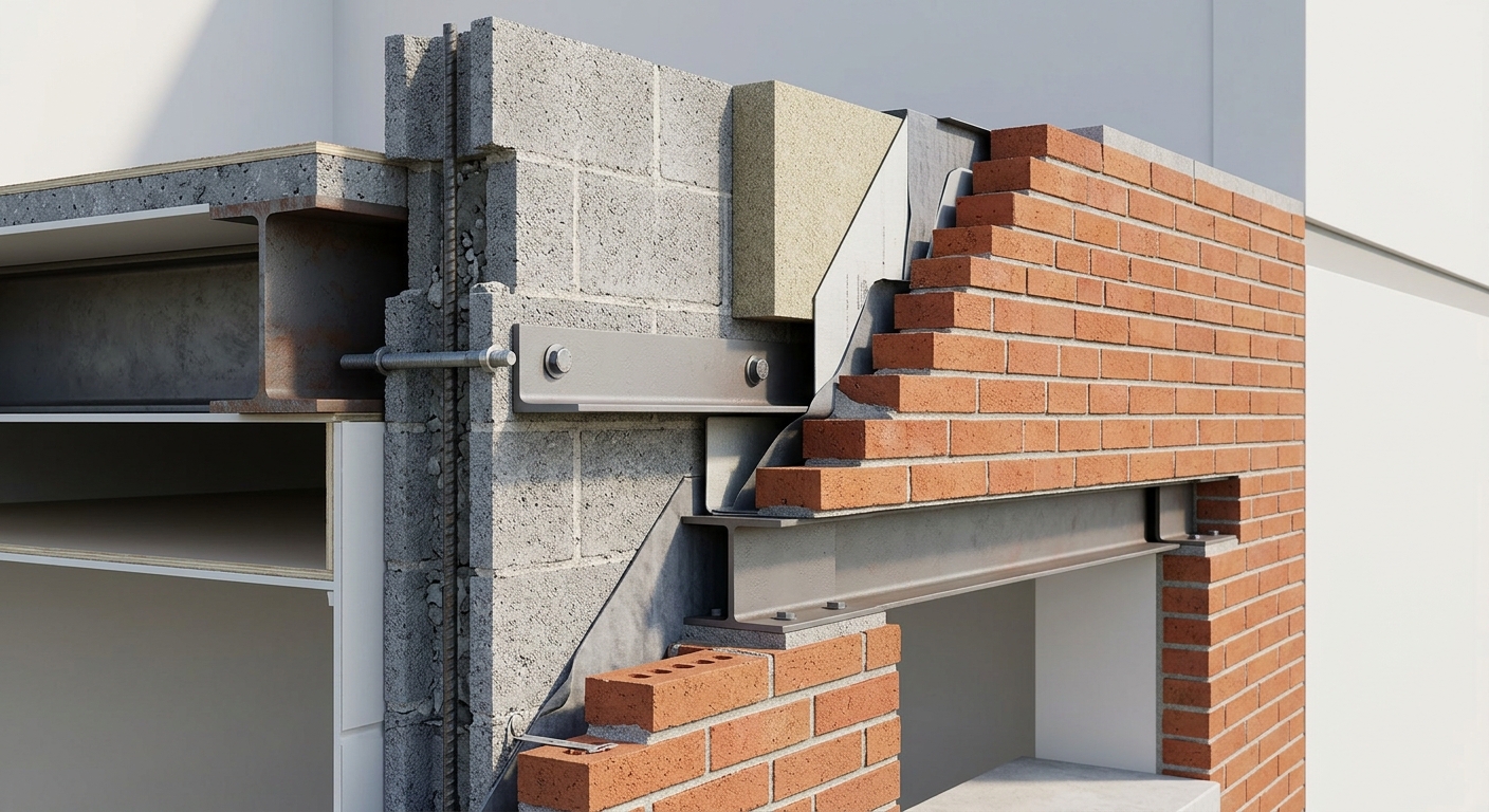
Structural steel and masonry frequently meet at openings, wall supports, floor edges, and exterior veneer conditions. That makes coordination important even when the packages are bid separately. Review structural and architectural details for loose lintels, shelf angles, bearing plates, anchors, embeds, wall openings, and steel supports that interact with CMU, brick, or stone assemblies.
For masonry contractors, these interfaces can affect wall sequencing, reinforcement, grout, flashing, anchors, access, and labor. A masonry estimate that reviews only architectural elevations can miss structural requirements shown elsewhere in the set.
That is why trade-specific masonry estimating services should coordinate architectural and structural documents rather than measure visible wall areas alone.
Turn the Drawing Review Into a Bid-Ready Steel Takeoff
Once the drawings have been interpreted, organize the quantities in a format that can be priced and checked.
A structural steel takeoff may separate:
- Beams and girders by shape and length.
- Columns by size and level.
- HSS framing and braces.
- Joists and joist girders.
- Plates and connection material.
- Decking and accessories.
- Miscellaneous metals.
- Shop and field labor.
- Coatings, freight, and erection requirements.
Where possible, connect quantities back to drawing references or marked-up plans so reviewers can verify the estimate before submission.
A quantity takeoff answers “how much?” A complete estimate goes further by applying material pricing, fabrication labor, erection labor, equipment, freight, subcontractor quotes, overhead, and other project-specific costs.
For contractors who need those quantities converted into a bid-ready cost breakdown, construction estimating services can help connect drawing scope with material, labor, equipment, and other project costs.
Final Checklist Before You Submit the Bid
Before closing the estimate, perform one coordinated review. Confirm that you checked the latest revisions, general notes, framing plans, elevations, sections, schedules, connection details, and specifications. Compare architectural openings against structural framing. Verify repeated members, alternates, and addenda. Document assumptions for incomplete connection information or unclear scope boundaries. Most importantly, make sure the takeoff includes small steel components and trade interfaces that are easy to overlook.
Learning how to read structural steel plans is not only a drafting skill. For an estimator, it is a scope-control process. The better you follow information from notes to plans, schedules, sections, and details, the more confidently you can build a complete bid.
Frequently Asked Questions
What should I read first on structural steel plans?
Start with the drawing index, title block, revision history, and general structural notes. Then review framing plans, elevations, sections, schedules, and connection details in a consistent order.
What does W18x35 mean on a structural drawing?
It identifies a wide-flange structural steel shape with a nominal depth of about 18 inches and a nominal weight of 35 pounds per linear foot.
Which drawings are most important for a steel takeoff?
Framing plans are usually the primary quantity source, but accurate takeoffs also require general notes, sections, elevations, schedules, connection details, and relevant specifications.
Why should a masonry estimator review structural steel plans?
Steel and masonry often interface through lintels, shelf angles, bearing plates, anchors, embeds, and framed openings. Reviewing structural information helps identify scope that may not be obvious on architectural wall plans alone.